advertisement
Robotic Arm: Movement Controller Software
The Raspberry Pi Arm kit is a 4 degrees of freedom manipulator robot. Its 4 servo motors are connected via a custom motor HAT that sits on top of the Raspberry Pi. This HAT is based on the PCA9685, an I2C motor controller. Using Python, we can program this arm.
In the last article, I showed how to implement a simple TCP-based client-server protocol that allows any client to send Python objects as bytes to the server via a two-stage header payload protocol. This article now explores how to actually control the 4 servo motors on the arm and provides valuable information and critical lessons learned.
This article originally appeared on my blog admantium.com.
Servo motor control on Raspberry Pi
For the PCA9685 hat motor that is compatible with Raspberry Pi, I found two libraries: Adafruit and Sunfounders. The Adafruit library is marked as deprecated, but if you configure the Raspberry Pi with the steps explained in my first article, it works out of the box.
To use this library, we will first install it using pip.
. Make sure you install it with Python 3; otherwise it may not work.
pip3 install adafruit-pca9685
Then connect a servo to any of the 16 ports, for example number 6. Open the Python answer on the Raspberry Pi and insert these:
from Adafruit_PCA9685 import PCA9685
pca = PCA9685()
pca.set_pwm_freq(50)
SERVO_NUMBER = 1
pca.set_pwm(SERVO_NUMBER,0,300)
The servomotor should move. Try putting other values instead of 300, in the range of 100 to 500, and you will see that the servo rotates to different positions. But what is the meaning of this particular value?
Essentially, servomotors are controlled by a set that defines the duty cycle of a PWM signal. Duty cycle defines the percentage of a PWM signal at which this signal is on. The most conventional hobby servo is the SG90, which has a frequency of 20 ms (=50 Hz) and can have a duty cycle of 1 to 2 ms. This information can be used to calculate the duty cycle as follows:
- Maximum 11-bit duty cycle value = 2024
- 50Hz = 20ms => 1 * 2024 = 2024
- 5Hz = 2ms => 0.1 * 2024 = 202.4
- 2.5 Hz = 1 ms => 0.05 * 2024 = 101.2
The PCA9986 library uses the formula in & 0xFF
, which effectively limits any input value to a maximum of 255. This value corresponds to 10% of 2024, which is the 5 Hz maximum of the servo motor.
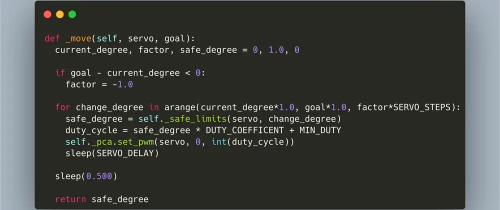
With this understanding, we can now implement motion commands for each servo.
Motion Features
Setting PWM values for servos is not the best mental model to work with. Therefore, I decided to work with degree values between 0 and 180. These values translate to the corresponding duty cycle values as shown here:
The next step is calibration. First, I send motion commands to each servo. The 90 degree value should be the center position of each servo. Therefore, I dismantled each joint, loosened the servos, and put the tip directly into the 90 degree position. After playing more with the joint fittings (so as not to lose or the servos can't handle the weight, not too tight or the servos won't move at all), it was done.
I continued to apply the full 180 degree movements to each joint. Naturally, not all movements make sense: the joint of the elbow can point upwards or even backwards. Since I don't plan on grabbing things from the air, this joint should only be able to move between 10 and 80 degrees. These limits are implemented as the next function to function as protection from all the commands I give to the arm.
def _safe_limits(self, servo, degree):
if servo == SERVO_X:
degree of return
servo elif == SERVO_Y:
if degree < 10:
return 10
elif degree > 80:
back 80
more:
degree of return
servo elif == SERVO_Z:
if degree < 15:
back 15
elif degree > 180:
return 180
more:
degree of return
servo elif == SERVO_G:
if degree < 23:
return 23
elif degree > 103:
return 103
more:
degree of return
more:
degree of return
advertisement
Related Articles


advertisement